Overview
The ApacheHVAC application is a user-friendly and yet very sophisticated tool for detailed, flexible, component-based HVAC system design, sizing, and modelling.
The ApacheHVAC user interface and system simulation are dynamically integrated with the ApacheSim thermal analysis and simulation. This is vital to providing a building-integrated approach wherein the HVAC system and building are assessed as a whole. All gains/losses, heat transfer, thermal mass in the building, infiltration/exfiltration, natural ventilation, and HVAC thermal and ventilation influences on every space are accounted for in concert with system performance.
- Detailed analysis of system design and energy saving measures.
- Model typical and innovative HVAC systems with minimal effort.
- Optimise HVAC operation and minimise energy consumption and carbon emissions: Get the system right for the building, budget, and environment.
- Simulate HVAC simultaneously alongside building thermal analysis.
- Create detailed airside and waterside plant loop/equipment models.
- Pre-defined HVAC system prototypes, an HVAC systems Wizard, autosizing, and multiplexing features save time and effort.
- Extensive capability for modelling custom systems and controls.
- Component-based HVAC system modelling is flexible, customizable, and mimics actual configuration, equipment, and control dynamics.
- Models heat recovery chillers, central plant heat pumps, integrated waterside economizers, and many other advanced options.
- Accounts for changes in fan power and energy with air filter soiling over time and with airflow through vs. bypass of HRV/ERV.
- Multiple systems and system types can serve any given zone.
- Combine with MacroFlo for analysis of mixed-mode operation combining natural and mechanical ventilation.
- Exceptionally well suited to modelling building-integrated and mixed-mode systems, including underfloor air distribution, double skin facades, passive downdraft chimneys, night cooling of hollow-core vented slabs, and earth-tube thermal pre-conditioning.
- Linked to 3D model to ensure the dynamic interaction between the building and HVAC system is correctly simulated: Direct interaction across thermal analysis, building loads, bulk airflow, solar shading, and HVAC systems.
- Simulation time steps down to 1 minute can be used to capture detailed dynamics.
- Users can also combine detailed and simpler, idealised HVAC models for different spaces within the same building model.
- System, Zone, and Room Loads Reports provide a comprehensive set of loads data, readily accessible in a compact yet clear and readable format.
- Reports, generated via Python scripts, can be automated.
- VistaPro provides detailed graphic and numerical results analysis for rooms, zones, all airside system nodes, and hundreds plant loop and HVAC equipment parameters.
Airside HVAC system modelling capabilities
Examples of typical and innovative systems or configurations that can be modelled in ApacheHVAC:
- VAV systems with state-of-the-art controls, air and water supply temperature resets, integrated airside and waterside economizers, demand-controlled ventilation (DCV), etc.
- Dedicated Outside Air Systems (DOAS) with room ventilation decoupled from room or zone heating and cooling via fan-coils, VRF, water-source heat pumps, radiant panels, DCV, etc.
- Active/passive chilled beams, 4-pipe beams, etc. with decoupled DOAS ventilation.
- Highly tailored airside system controls and configurations (e.g., for labs or healthcare)
- Cascading airside systems, such as recirculation air from office systems providing make-up for laboratory fume hoods, or hotel room PTAC units drawing air from a central atrium served by a VAV system for the common areas.
- Floor-by-floor air-handlers sharing a common DOAS for tempered ventilation air
- Air-source heat pumps, DX cooling, and unitary cooling (split systems)
- Indirect-direct evaporative cooling systems (IDDE), desiccant-based air conditioning, and daisy-chained indirect evaporative to achieve supply temperature below OA wet-bulb
- Hybrid hydronic/air systems, radiant chilled/heated floors, ceilings, and panels
- Underfloor air distribution (UFAD), with thermal stratification in cooling mode, mixing (destratification) when heating, fan-powered boxes for perimeter zones, and both radiative and conductive heat transfer via/through raised floor, floor/ceiling decks, and plenums
- Thermal displacement ventilation (DV), including thermal stratification per heat gains
- Vented stack-effect double-skin facades and zonal modelling of glazed atria
- Hollow-core slab systems, thermal labyrinths, and earth tubes
- Passive downdraft evaporative cooling via stack-effect chimneys
- Mixed-mode systems with integrated control of mechanical and natural ventilation
- Natural ventilation plus CO2-based demand-controlled mechanical ventilation, active chilled beams, and radiant heating and cooling panels working together as an integrated system
Waterside and HVAC equipment modelling capabilities
Examples of typical and innovative systems or configurations that can be modelled in ApacheHVAC:
- Central plant heat pumps serving HWL, CHWL or both (when reversible) with innovative UI for multiple heat pump instances and advanced autosizing options
- Downstream auxiliary heat source (boiler or other equipment) for backup/supplement of entire HWL or for upgrading or maintaining SWT on just one of multiple secondary loops
- Detailed air-to-air heat pump modelling, including lockouts, defrost, crankcase heat, etc.
- Variable Refrigerant Flow (VRF) with heat recovery, water-source, and air-source options
- Heat recovery chiller for moving heat from chilled water loop to hot water loop
- Chilled water loops with constant, staged, or variable flow; single or dedicated pumps; independent primary and secondary loop temperature setpoints and reset controls; pre-cooling via water-source heat exchanger, dedicated cooling tower or fluid cooler, or integrated waterside economizer
- Ice and chilled-water thermal storage for chilled water loops
- Condenser water loops with any number of cooling towers or dry/wet fluid coolers; single or dedicated pumps; constant, staged, or variable flow; waterside economizer; and heat recovery to hot water and heat transfer loops
- Free convection for cooling towers / fluid coolers at low flow fractions
- Hot water loops with constant, staged, or variable flow; single or dedicated pumps; pre-heating via air-to-water heat pump, combined heat & power, solar water heater, or condenser heat recovery; downstream auxiliary/supplemental/backup heat source
- Multiple secondary hot water loops with advanced features, including independent secondary loop temperature control (setpoints and reset schemes) for cascading SWT
- Scheduled loads components on HWL and CHWL for process loads or plant-only modelling
- Heat transfer water loop serving zone-level water-to-air heat pumps or water-source VRF with floating loop temperature control, all heat source and heat rejection options as on HWL and CHWL, plus water-source heat exchanger for heat acquisition/rejection.
- Radiator and chilled-panel/hydronic-loop performance per HW/CHW temperature and flow
- Domestic Hot Water (DHW) with multi-pass configuration, storage tank losses, optional recirculation and/or pre-heating, including solar water heater, condenser heat recovery, or drain water heat recovery (DWHR)
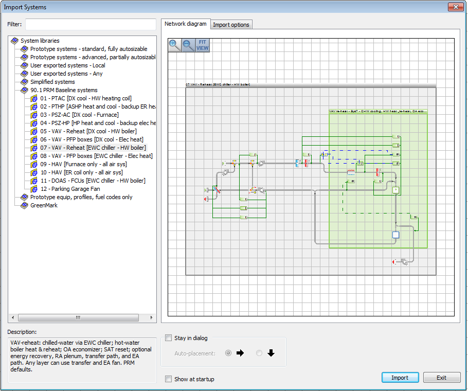
HVAC Systems Wizard
HVAC system selection and sizing is streamlined and can be easily completed with minimal steps:
- A simple and intuitive UI provides system creation, zone assignment, equipment selection, loads calculations, autosizing, and loads reports.
- Zoning, airside, and waterside configurations are selected from organized tree and lists.
- Graphic illustration of systems support understanding of each airside configuration.
- Complete HVAC systems, including proposed & baseline for code compliance and ASHRAE 90.1, plus ASHRAE loads calculations, sizing, and reports are created in minutes.
Detailed editing of all system and equipment parameters, system modifications, and re-sizing as needed can follow at any point thereafter.
Multiplexing
This unique functionality provides exceptional productivity in editing ApacheHVAC system details. Engineers can readily assign HVAC zones, associated return and/or supply air plenums, and data for numerous equipment and controls parameters to very large, complex system models. Multiplexing layers and tabular editing facilitate fast and accurate data population with editing at global, system, zone selection set, or individual zone levels.
Integrated System Management
The Integrated System Management (ISM) interface is a simplified approach to accessing detailed HVAC system modelling parameters, making the use of ApacheHVAC easier and more efficient when reviewing and editing system details. It also provides links to room and zone settings and inputs from thermal templates and space data in the building model. A single dialog and tabular interface provides user-friendly access to editing inputs and viewing derived values for all significant airside HVAC system parameters.
System Parameters
- Review and edit all significant airside system parameters within a single tabbed dialog
- Set and modify schedules and system behaviour during unoccupied hours
- Determine the basis for airflow autosizing, controls, terminal units, etc.
- Extensive tools and flexibility for ventilation, exhaust, and transfer air configurations
- Support for ASHRAE 62.1 Appendix A and ASHRAE 170 for Healthcare
- Visual and text feedback for status of system edits, errors, and autosizing
System Parameters links
- A robust and user-friendly system of selectable links for coupling the System Parameters dialog to a broad range of component and controller applications
Zones Tabular Edit
- User-configurable spreadsheet-like tabular interface for editing, review, and QA
- Includes all editable and derived parameters from the System Parameters dialog
- Conditional formatting for ventilation OA fractions and to highlight critical zone
- Import and export from external spreadsheets
Zone Airflow Distribution
- Spreadsheet-like tabular interface for editing, review, and QA of room and zone heating and cooling loads, room percentages of associated zone airflows, and designation of master room within each zone
User Interface for systems editing and review
Easy to use interface and component graphics provide fast and easy editing, customization, and autosizing of HVAC systems.
- Comprehensive toolbars and menus within the HVAC interface include:
- Prototype HVAC Systems and Plant Equipment libraries and HVAC System Wizard;
- System Parameters, Zones Tabular Edit, and Zone Airflow Distribution dialogs
- All airside components, controls, plant equipment, and waterside loops;
- Performance Curves library;
- Network checks, Zoning checks, and Find-node;
- Room/Zone Loads, System Loads and Autosizing, and Loads Report generation;
- User preferences and help links to user guides and other information.
- Import and export functions for loading, saving, and retrieving pre-defined and customized systems and equipment to and from the HVAC systems library
- Waterside plant loops, equipment, and controls are set up in clear, menu-driven dialogs
- Airside components and controls are placed, moved, and copied with drag & drop functions and can be individually edited via component and controller dialogs.
- Equipment that will be used in multiple instances can be defined just once and then applied
- Chiller Performance Curve library with generic and manufacturer model-specific curve sets:
- View fundamental characteristics and 2D and 3D plots of curve set and each curve
- Copy, edit, and define curves
- Airside network drawing tools and stretchable controller leads provide straightforward modification and tidying of the configuration and layout of airside networks
- Visible logical AND/OR connections support controller interactions and override functions
- Annotation tools for adding labels and descriptions on airside and waterside system views
Prototype Systems Library
Pre-defined prototype systems require minimal user input and provide increased productivity. With fully editable pre-defined configurations, controls and equipment fully compatible with ISM, this library offers a valuable starting place for building custom systems.
- Packaged terminal units
- Packaged terminal air-conditioning with DX cooling and hot-water loop (PTAC)
- Packaged terminal heat pump with DX cooling and air-source heat pump (PTHP)
- PTAC/PTHP variants for three different fan, ventilation, and exhaust configurations
- PTAC/PTHP variants using detailed unitary cooling equipment model
- Single-zone air-conditioning units (CAV or VAV)
- DX cooling and direct-fired gas furnace heating
- DX cooling, gas furnace, and CO2-based demand-controlled ventilation (DCV)
- Cooling-only computer-room AC (CRAC)
- Cooling-only computer-room air handler using chilled water (CRAH)
- DX cooling and air-source heat pump and electric-resistance backup
- Multi-zone VAV-reheat systems (can also run as CAV)
- DX cooling and hot-water coils (HWL including boilers and/or heat pumps, etc.)
- DX cooling and parallel fan-powered (PFP) boxes with 2-stage electric re-heat
- Water-cooled chiller(s), chilled-water coils, and hot-water coils
- Water-cooled chiller(s), chilled-water coils, PFP boxes with 2-stage electric re-heat
- Systems combining standard VAV boxes and PFP boxes for different zones
- VAV with heat recovery chiller for coincident chilled- and hot-water loads
- Chilled-water AHU coil and series fan-powered boxes with electric re-heat
- Advanced VAV with system outside air reset per continuous A62.1 evaluation
- Multi-system networks with a VAV system serving common spaces and PTACs drawing make-up and ventilation air for individual rooms from the common spaces
- Indirect-direct evaporative (IDDE) cooling VAV system with HW reheat
- 2-stage IDDE cooling and CO2-based DCV
- 2-stage IDDE cooling with DX coil upstream of DEC
- Dedicated outside air system (DOAS) with a range of possible zone-level units
- Hot and chilled-water (4-pipe) fan-coil units
- Active chilled beams and fin-tube convectors or radiators
- Four-pipe active beam induction units for both heating and cooling
- Air-source VRF
- Water-source VRF
- Water-loop zone-level heat pumps
- Demand-controlled ventilation (DCV) based on CO2 levels and/or occupancy
- Tempered OA fed separately to spaces (decoupled ventilation) or via terminal units
- Mixed-mode system: integrated control of mechanical and natural ventilation/cooling
- Integration of setpoints in control profiles for fenestration openings and HVAC airflow in mixed-mode mechanical plus natural ventilation/cooling system
- Laboratory 100% OA system with airflow setback during unoccupied hours
- Multi-AHU system networks sharing a common DOAS to supply tempered OA to the AHUs
- Chilled and heated ceiling panels with DOAS
- Passive chilled beams with DOAS
- Dual-fan, dual-duct VAV with zone-level mixing
- Underfloor air distribution system
- UFAD supply air plenum thermal zone
- Separate occupied and stratified zones
- Heat-pipe to deliver dry, moderately cool air
- Underfloor series/parallel fan-powered boxes
- De-stratification of space with heating airflow
- Fixed or variable-volume diffusers
- Leakage path to return
- Heat & vent systems, parking garage fan systems, etc.
- Simplified systems for quick, early-stage modelling
- User exported systems or any subsets/components thereof
- Create, modify, and save custom systems to local and shared user HVAC libraries
- Use import/export capabilities to load those systems for any project
- Baseline HVAC systems for numerous compliance programs:
- ASHRAE 90.1 Appendix G Performance Rating Method
- ASHRAE 90.1 Energy Cost Budget Method
- California Title-24
- NECB
- IECC
- UK NCM
- GreenMark
Input Data
- Operation schedules, profiles, and setpoints
- Airside component parameters: coil performance, fan performance, heat exchanger effectiveness, spray chambers and humidifiers, damper sets, duct gains and losses, etc.
- Central plant part-load efficiencies, loop configurations, and controls
- Radiator and chilled panel characteristics
- Controller parameters:
- Sensed and controlled variables
- On-off or proportional
- Fixed or variable set-points
- Set-points linked to other simulation variables via ‘formula profiles’
- Boolean logical AND & OR inputs from other controllers
Loads Reports
- Comprehensive loads reporting for Rooms, Zones, HVAC systems, Plant loops, Equipment
- Independent sizing runs and reporting for Room/Zone loads analysis and basic airflow calculations (no system required) with results provided in both PDF and spreadsheet formats
- System Loads & Sizing Reports based upon actual system simulation at design conditions:
- Generate reports for any new or existing System Loads and Sizing results file
- Set relevant coils for determining the time of system/zone Heating & Cooling peaks
- Include or exclude oversizing factors
- Reports include:
- Project and climate (building, design weather, etc.)
- Plant loops & equipment (equipment capacities, flows, etc.)
- Space loads & ventilation (system summary)
- Detailed loads breakdown, coil capacities, airflows, engineering checks, etc., at system, zone, and room levels
- VE2016 System Sizing report
- ASHRAE 62.1 Ventilation (Appendix A method) report
Outputs, Results Analysis, and Data Export
- Results displayed in VistaPro, along with the weather data used to drive the simulation
- A wide range of tables and graphs are produced for results analysis including XY plots, monthly summaries, ranges, tables, user-specified synopses, and psychrometric charts.
- Airside component-level outputs suitable for design and control optimization as well as use in component selection and duct sizing, include:
- Air flow rates, temperatures, and humidity
- Performance for each coil, fan, humidifier, etc.
- Air handling component loads and heat/energy recovery
- Duct heat loses and gains, fan heat gain, etc.
- Component psychrometric processes
- Room unit loads and performance
- Component level plant loop and equipment output
- Hundreds of detailed parameters results for numerous aspects of each water loop and each piece of plant equipment, from chillers and cooling towers to boilers and pumps to water-source VRF units on heat transfer loops.
- System performance indicators
- System energy broken down by component or fuel
- Carbon emissions
- Performance at each node in the airside HVAC network in terms of air dry-bulb and wet-bulb temperatures, mass flow, volume flow, moisture content, relative humidity, and CO2 concentration
- Room and zone performance indicators, including:
- Room temperatures: air, mean radiant, dry resultant
- Manual and automated (report mode) analyses of Unmet Load Hours (UMLH)
- Comfort indices: predicted mean Vote (PMV) and percentage of people Dissatisfied (PPD), with detailed room template level inputs for clothing and activity levels, elevated air movement, and occupant exposure to short-wave radiation, etc.
- ASHRAE Std 55 Comfort analyses, including PMV/PPD method, Adaptive Thermal Comfort Method, and option for occupant receiving direct solar radiation.
- Room loads: heating, cooling, humidification, dehumidification
- Load breakdowns: internal/casual gains, solar gains, conduction and infiltration gains and losses, ventilation, system, and plant inputs
- Surface temperatures and radiant heat transfer
- Energy Consumption: Annual, Monthly, Hourly for equipment, systems, and building
- Multiple results can be displayed simultaneously or aggregated
- Results can be displayed in both metric or inch-pound (IP – U.S.) units
- Results can be exported to other windows applications for use in reports, presentations, spreadsheets, and further analysis
- Equipment schedule can be exported in CSV format from HVAC system wizard


 NL
NL


